SHIGGSY

Expert Class
Posts: 128
|
 posted August 18, 2007 12:21 PM
 Edited By: SHIGGSY on 18 Aug 2007 13:30 Edited By: SHIGGSY on 18 Aug 2007 13:30
Multiple Electrical Issues
*&$%£"&*ing elecronics!
Thought I'd put all four in one thread incase they are related.
First off, the battery is fine, it always reads good voltage, it's been load tested, it's fine.
1) Low voltage at running speeds. Voltage doesn't rise as speed increases. At tickover its about 13.8v, cruising along it will be between 13 and 13.5, though it occasionally it can drop to 12.9. Stator output is fine, 60v AC at tickover, 117v AC at 4000RPM.
The feedback wire into the Regulator reads:-
Ignition on - 12.7V
Tickover - 13.8
4000rpm - 13.5 - 13.7
pretty much identical to the battery.
The Regulator output wires read
Ignition off - 12.9v
Ignition On - 12.7v
Tickover - 14v
4000rpm - 13.8
again almost indentical to the battery, though it should be up around 14.2v - 15.2v
The regulator checks out on all checks apart from,
(a) voltage rising when revs increase,
(b)Resistance check. Resistance one way through the regulator with ohms set at 20k measure approx 3.4, back the other way accoring to the manual should be 10 times higher. I can't get a reading at any ohm level. So manual says replace regulator.
But, I have discovered though that If I put a 20k variable resistor inline with the feedback wire I can get the output voltage from the regulator to rise up to 15.1v. ?????
I have another regulator which I double checked the resistance check, on that one at 200k I can get a reading aback the other way in the 60 range, tough one leg is down around 25. Ip this one on the bike, same problem and with this one the inline resistor didn't make a difference.
2) Problem Starting. This started when I put a new cam sensor in, the starter motor will try turn the engine over a few turns pause, bit more, pause, blow pressure out of the exhaust, or out of the inlets (can feel pressure blow out of the airbox holes where the rubber inserts of the ram air covers connect). You can here the hum of the starter motor trying to turn the engine over when it pauses and I can see the voltage drop to apprx 8 volts.
It does this hot or cold. I pulled the starter motor and found the brushes needed replacing, put new ones in, no change. Got another starter motor off ebay as it was dirt cheap, opened it up, it was fine, put it on the bike, no change.
The thing I have discoved is that if I start the bike with zero revs, just hit the start button, she fires up fine straight away, give it any amount of throttle at all, (including the choke\fast idle lever) then its back to popping and farting and pausing and not wanting to start. ??????
One fired up and running it's fine not including (3) and (4) below.
3) Intermittent rough running came back one evening last week. In the mornng I disconected the ECU blocks, twisted them both 360 degrees and put them back. Things improved it looks like I have a broken wire somewhere, I think.
4) Also started when I put the new cam senor in, vicious jerking at about 2100 rpm on a closing throttle or partly opened throttle.
....help.....
  
|
aughtsix
Expert Class
Posts: 277
|
 posted August 18, 2007 01:16 PM
Shiggs -- Do you suppose any of this relates to your earlier stator issues?? As I recall you had *several* stators in and out, along with regulator/rectifiers. A couple of your stators looked like they'd spent a couple of hours on a cajun barbeque...
|
SHIGGSY
Expert Class
Posts: 128
|
posted August 18, 2007 01:39 PM
ah, saw that did you  Your guess is as good as mine, the stator that's in there now went in the same time as the regulator and battery, all oem, and it's been fine about 8k miles now I think. The previous stator (a rewound one) lasted about six miles before turning into someting resembling a meteorite, no one knows why. That one had new a pattern regulator (the one I tested above) and a new battery (also load tested recently and also fine). Your guess is as good as mine, the stator that's in there now went in the same time as the regulator and battery, all oem, and it's been fine about 8k miles now I think. The previous stator (a rewound one) lasted about six miles before turning into someting resembling a meteorite, no one knows why. That one had new a pattern regulator (the one I tested above) and a new battery (also load tested recently and also fine).
|
ridgeracer

Pro
Posts: 1309
|
posted August 19, 2007 07:14 AM
Edited By: ridgeracer on 19 Aug 2007 08:31
Ok lets tackle #1
There are two distinct parts to the Regulator: a) A rectifier to convert the alternator AC to DC and b)A regulator to limit the output voltage to the correct value.
Lets start with the rectifier. It uses diodes which are the electronic equivalent of check valves. They only allow current to flow through them in one direction or polarity. Here is an example of a three phase rectifier.

In this image Y1, Y2, Y3 would be connected to R, S, T.
Now when the alternator is spinning the voltage on the Y wires ALTERNATE between positive and negative but at different times in relation to each other. At some moment in time Y1(R) will be positive and Y2(S) negative. Referring to the image above when Y1(R) is more positive than output + current flows thru the diode above R to output +. The diode below R is off or closed because current only flows in the direction of the arrow.
However because at this moment Y2(S) is more negative than output - current will flow through the diode below S because in effect output - is more positive than the more negative Y2(S). As the three Y wires alternate at some point at least one of the three upper diodes is conducting current into output + and at least one of the lower diodes is conducting current away from output -
So how do you test this rectifier? Well its pretty simple because when its functioning it should only conduct current in one direction. This is where the manual gets the low resistance in one direction and more than ten times the resistance in the other direction" It does the job but I would have gone into more detail.
Specifically, again referring to the image above, When you put the RED or positive lead of your meter on Y1(R), Y2(S), or Y3(T) and the BLACK or negative meter lead on output + (W/R1, W/R2) it should read low resistance as the diode your testing should be on because your measuring with R,S, or T more positive than output +. If you swap the red and black leads the top diodes will be off and resistance should be very high.
To test each of the bottom three diodes put your BLACK lead on Y1(R), Y2(S), or Y3(T) and the RED lead on output - (BK1, BK2). This should read low resistance because the diode your measuring should be on as your measuring with output - more positive than R,S, or T. Swap the red and black and you should get very high resistance.
Now you said in your post....
quote:
Resistance check. Resistance one way through the regulator with ohms set at 20k measure approx 3.4, back the other way accoring to the manual should be 10 times higher. I can't get a reading at any ohm level.
Remember the manual says "...MORE than 10 times the value". Isn't 100 times or even 1000 times 3.4k MORE than 10 times 3.4k ohms? If you test the rectifier as I described above noting the red and black polarities and it reads low when the diodes are supposed to be on and very high or overrange when the diodes are supposed to be off than I say your rectifier is probably good especially if your using a meter in ohms mode. You should use one with a diode check mode.
As for your lack of voltage or charge:
Three phase permanent magnet alternators have some weird properties. Consider the image below. It is not a three phase waveform but you can get the general idea.

The bottom image in blue is what should be coming out of your rectifier (not regulator) one positive impulse from each lead Y1, Y2, Y3, Y1, Y2, Y3, Y1, Y2, Y3, Y1.....etc.
Now the weird part is if you lose just one of your Y connections the alternator doesn't just quit. Instead it looks like the middle image in green. Only instead of missing half of the impulses it would be missing 2 out of 3. It would be like a three cylinder engine running on one cylinder, yeah it might run, but its not going to have any power.
You would see some voltage but running at only 33% duty cycle your not going to have the current needed to run the bike and charge the battery so you won't see the voltage get very much above the battery voltage. To charge the battery the alternator needs to make enough energy to handle all the bike load plus have extra left over to charge the battery. In other words you need sufficient current to raise the system voltage over the battery voltage
Now the problem measuring such a one out of three pulse waveform with a meter set to AC volts is that it will still read pretty much the same as it would on the bottom 3 out of 3 waveform. The meter measures average peak voltage and is not designed to register changes in duty cycle.
So when you say....quote:
Stator output is fine, 60v AC at tickover, 117v AC at 4000RPM.
...did you measure all three leads? Did you measure and have that voltage across
Y1 to Y2
Y1 to Y3
Y2 to Y3

|
SHIGGSY
Expert Class
Posts: 128
|
posted August 19, 2007 08:07 AM
Edited By: SHIGGSY on 19 Aug 2007 09:08
Hiya,
(another answer to archive )
For completeness my measurements were :-
Neg To WR1 Pos To Y1 3.37
Neg To WR1 Pos To Y2 3.43
Neg To WR1 Pos To Y3 3.4
Neg To WR2 Pos To Y1 3.4
Neg To WR2 Pos To Y2 3.51
Neg To WR2 Pos To Y3 3.46
Pos To BK1 Neg To Y1 3.36
Pos To BK1 Neg To Y2 3.45
Pos To BK1 Neg To Y3 3.45
Pos To BK2 Neg To Y1 3.37
Pos To BK2 Neg To Y1 3.46
Pos To BK2 Neg To Y1 3.47
Measurements back the other way were all 1 i.e. Pos To WR1 Neg To Y1 etc
Yes AC Voltages were read :-
Y1 - Y2
Y1 - Y3
Y2 - Y3
My multimeter does have a Diode function on it though I have never used it ( never been to sure about it how to use it). I've also recently aquired a 2 channel scope meter and an amp clamp, though not much ability, but if you want me to go out and measure something then fire away.
If you think the regulator is ok I'll go with that, I did the three batteries and the lightbulb test (9 volt batteries) and that all checked out ok.
Thanks
|
SHIGGSY
Expert Class
Posts: 128
|
posted August 19, 2007 08:24 AM
Edited By: SHIGGSY on 19 Aug 2007 09:26
Incedentely,
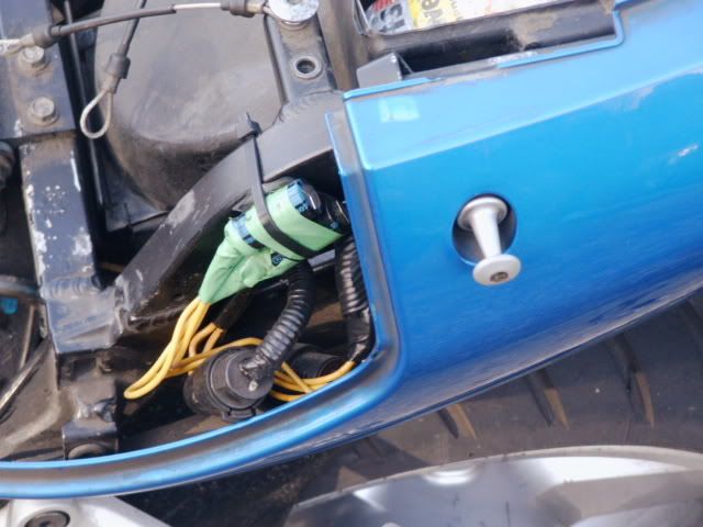
I've spent the day checking the EUC wires, when I pulled one of the ground wires out the cap on the end that keeps the internal connection tight to the ecu male connectors stayed in the housing (the bit right on the end).
(ripped off one of your phtos here ridgeracer)
It was a pig to get out and was unusable when it did emerge, but I'm hoping because it was loose that maybe that is my intermittent poor ecu connection issue. I had to hold the internal connector closed and drop a bit of solder on it to try an keep it shut and maintain a tight connection when it was pushed back in. Wouldn't be the first time I've had a poor connection inside a perfectly healthy looking connection block.
|
SHIGGSY
Expert Class
Posts: 128
|
posted August 20, 2007 11:22 AM
Edited By: SHIGGSY on 20 Aug 2007 12:24
quote:
Ok lets tackle #1
Ok, I read your post about 20 times and some of it got through. The 'what should be coming out of your rectifier (not regulator) ' comment threw me a bit as I couldn't see how I would access the raw rectified signal when its buried in the R/R and all I had access to was the regulated output and the stator input, but obviously that wasn't what you ment.
Anyway I have some Stator line waveforms. Looks like there is a problem, but I don't know how significant it is.
This is Y1
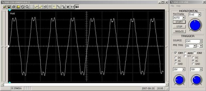
All three wires look the same in isolation, heres one of Y1 and Y2
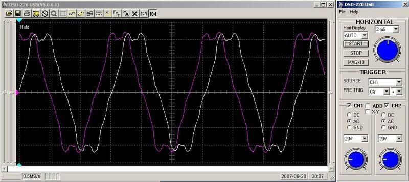
Not knowing any better I'd hazard a gueess that I have a magnetic weak spot in my rotor.
This is a shot of one of the two power wires coming out of the regulator.
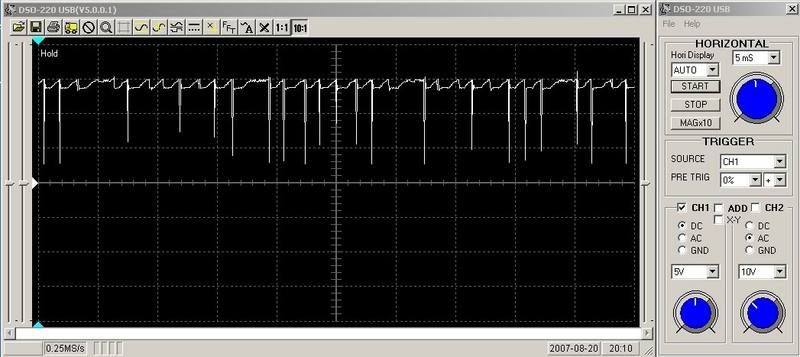
No idea if that's good or bad ?
If there is a way of creating your 3rd image (rectified output) I don't know how to do it.
Any thoughts ?
|
capt10ed
Expert Class
Posts: 327
|
posted August 20, 2007 12:47 PM
concerning problems 2, 3 & 4. Did you pull the cams? If you did your timing is off a bit. If not, it is possible that the position sensor is defective or machined incorrectly. Since the problems started at that timeI would look Carefully at it.
____________
2014 Loring AFB 14 runs over 200mph
with a best of 208.1 in 1.5 miles
and 204.5 in the mile.
|
thekaz

Needs a job
spell chequer is bustimicated
Posts: 2909
|
posted August 20, 2007 03:53 PM
definately fix the charging issue first as the sensors maybe looking for more referance voltage......
|
shiggsy
Expert Class
Posts: 128
|
posted August 21, 2007 12:03 AM
quote:
concerning problems 2, 3 & 4. Did you pull the cams? If you did your timing is off a bit. If not, it is possible that the position sensor is defective or machined incorrectly. Since the problems started at that timeI would look Carefully at it.
Cams came out about 5000 miles ago and was fine until recently when it wouldn't start. Scoped the cam sensor and it was a very irregular blip, new cam sensor got it starting and running better than previously. The startup problem seems timing related but only if the throttle is opened which tends to indicate that the TPS voltage might be having an effect somewhere which may also be tied up with the jerking at at 2100rpm. I have scoped the TPS output voltage at the ECU as the throttle is opened and closed it looks ok, nice smooth curve.
I agree with kaz though to try and sort the charging system first. Just to confirm I scoped the Stator wires with the +probe on Y1 grounded to Y2 same way as a DVM, I presume that's correct ?
|
ridgeracer
Pro
Posts: 1309
|
posted August 21, 2007 09:05 AM
Given what I see on your scope output I don't see anything wrong with your charging system. The dips at the peaks of the alternator output are nothing to worry about and your regulator output looks normal. The max output is limited to 15V and it never falls to low (not including the noise spikes) and averages above 13.8.
Your readings are within 3% of normal I thing your looking in the wrong place.
|
SHIGGSY
Expert Class
Posts: 128
|
posted August 21, 2007 10:28 AM
Thanks for the reply. The regulator output on that waveform is at tickover which it normally does read at 13.8v. The problem, as I understand it, is that the voltage should increase as the revs rise but it actually falls, 12.9 to 13.5 when I'm cruising along. At tickover with the brake light on is the only time it'll actually jump up to 14.2. Shouldn't the regulator be ouptutting about 2 volts more, upto a maximum of about 15v, than it's receiving though the feedback wire, at 4000rpm its outputting about 0.1v more than its getting in. Is that correct ?
|
shiggsy
Expert Class
Posts: 128
|
posted August 28, 2007 03:56 AM
Edited By: shiggsy on 28 Aug 2007 05:03
Ok I have sorted out the low voltage issue, I think I tripled wammied myself.
(basically ridgeracer was right, right and right again).
The current setup was a relay fed off the the ignition wire to power my Digital Voltmeter (DV) and accessory block.
Wammy1:
I discovered with the engine running that the DV was reading .3 volts less than at the battery terminals when checked with a handheld DVM. I had the DV ground going to the headstock bolts (paint removed). When I moved the ground point to the main frame ground the reading became equal. So that lifted my voltage reading slightly, still had a low reading which fell when the revs rose though. I then moved the ground point for the DV direct to the battery neg terminal.
If the following is incorrect please chip in and say, I don't want to put inaccurate info into a thread.
The regulator outputs voltage based on the voltage it has available to output from the stator and the draw on the system by the bikes electronic requirements (via the brown feed back wire going into the regulator). If the battery is low the regulator doesn't know about it, if it is high the regulator doesn't know about it. It only knows the feedback wire.
Wammy2:
The accessory block was a direct drain from the battery (lowering the voltage readout). By removing the accessory block the battery voltage reading went up again.
Wammy3:
When the accessory block fed from the battery the regulator didn't know anything about it and didn't compensate for it. The brown wire that runs from the ignition splits into three just before the junction box, 2 wires head into the junction box, the third then runs straight back to the regulator (the feedback wire) I therefore tapped the accessory block into the feedback wire after the junction block, the regulator now registers this extra draw and output more voltage to compensate and therefore pumping a higher charge into the battery, giving me yet another higher reading.
The problem with that was I was back to the problem which caused me to move the accessory block off the ignition wire in the first place, noise on the line( downward spikes) causing the digital gauges to dance. So I used ridgeracers suggestion stabilizing the voltage signal http://www.bikeland.org/board/viewthread.php?FID=1&TID=33154
I didn't use a choke and could only get a 2200uf 50v capacitor but when I put that inline prior to the accessory block it did the job. When I checked it with a scopemeter it was the same but the downward spikes had disappeared. (I think I'll do the same thing on the regulator output wires and try to cure it at source).
The result is I now have 13.95v at cruising speed as opposed to anywhere between 12.9 and 13.5v. The reading also now has a fluctuation range of about .03 volts as opposed to about .90 volts and when I do something like turn my heated hand grips on the voltage goes up to about 14.25 instead of dropping half a volt.
So Scratch #1
(btw I think the double dips in the sine wave peaks and troughs above is Harmonic Interference from the other sine waves ).
|
SHIGGSY
Expert Class
Posts: 128
|
posted November 04, 2007 09:03 AM
Edited By: SHIGGSY on 4 Nov 2007 09:11
All 4 issues now solved at last.
Number 1
(voltage) was solved above.
Number 3
(intermittent rough running) I solved months back by putting a couple of capacitors between the voltage regulator and the the rest of the bikes electronics to get rid of the voltage spikes. I called success on this several times only to have it come back soon after but it's never been back since I did this.
Number 2
(starting issues, back firing, forward firing compression locking) and
Number 4
(surging\jerky as hell between 1800 and 2400 rpm)
This was the simply the crank sensor which I think I broke trying to solve number 3.
http://www.bikeland.org/board/viewthread.php?FID=1&TID=33278

I have scoped the crank sensor several times but it always looked fine. This weekend I thought sod it and fitted a selection of 2nd hand sensors that I have been collecting off eBay for several months. After each sensor I tried the bike. Crank sensor was of course the last one and she fired up with no problems at all and the surging has gone as well.
|
|
|
|
|
 HOME
HOME NEW TOPIC