BrooklynNYZX12

Zone Head
Posts: 520
|
 posted October 27, 2007 06:12 PM
Does the car formula of the exhaust flow #'s within a certain percentage of intake flow #'s (70-75%)hold true for the bike motors?Isn't some reversion necessary in the combustion process?I think too good of an exhaust port isnt good like jw mentioned above..over exhausting?
____________
Orient Express Top Street Bike Winner 8-4-07
  
|
dubious

Needs a life
Needs more time to ride!
Posts: 8442
|
posted October 27, 2007 06:27 PM
yes, excess scavenging is not good, because it allows the intake charge to blow down , and out the exhaust, during valve overlap...
Some backpressure is required to keep the fresh charge in the cylinder.
Ideally the cam profile is matched with the port flow, so the ports are no larger than necessary, to keep velocity high at lower rpm, yet flows to the potential of the cam at top rpm.
Some porting techs are reporting RWHP increases of 10-12 rwhp, heads only, no cams!
What does the entire curve look like though...
Again I am no porting pro, just an avid enthusiast, looking for any opportunities to learn more, and an advantage!
Thanks for sharing !
____________
natural selection.....
destiny will overcome intervention.
Some are not worthy of the effort.
|
Y2KZX12R

Needs a job
CompetitionCNC.com
Posts: 3762
|
posted October 28, 2007 05:49 PM
quote:
D shaped is better. I've seen flow suffer a lot taking material off the floor of an exhaust port.
I was asking about inside the factory header pipe not the head.
Yes, you want about 70-75% exhaust flow on a 4 valve engine. A smaller exhaust port can enhance low and midrange torque at the expense of top end power. Similar to a smaller intake port.
Over scavenging is caused by poor EVC timing and or from too much valve overlap, not exhaust port volume or flow rate. The over scavenging happens as the exhaust valves are just about closed and the flow volume in the port is very low. An improperly designed header can cause it as well but usually only at a particular rpm and it usually shows up in the a/f ratio chart.
____________
Y2KZX12R
CompetitionCNC.com

|
dubious
Needs a life
Needs more time to ride!
Posts: 8442
|
posted October 28, 2007 06:09 PM
so is it the shape of the exhaust ports that suck, or the diameter near the outlet?
Is the restriction at the valve pocket or the outlet on our bikes?
Thanks again.
____________
natural selection.....
destiny will overcome intervention.
Some are not worthy of the effort.
|
Y2KZX12R
Needs a job
CompetitionCNC.com
Posts: 3762
|
posted October 29, 2007 03:40 AM
The port volume seems ok, but the shape needs work. I'll know more in a few weeks once I start to work on it.
____________
Y2KZX12R
CompetitionCNC.com
|
Y2KZX12R
Needs a job
CompetitionCNC.com
Posts: 3762
|
posted October 29, 2007 05:20 AM
Seat geometry is also important for increased VE at all rpms. Heres a profile of one of our seat designs (not zx14) that makes nice improvements in VE on that particular engine.
____________
Y2KZX12R
CompetitionCNC.com
|
ninja12
Needs a job
Posts: 3310
|
posted October 29, 2007 11:02 AM
care to explain?
|
jw
Novice Class
Posts: 81
|
posted October 29, 2007 12:21 PM
Oh, all it is is a picture of a valve with a 3-angle cut and the valve seat cut correspondingly.
Instead of a strict three angles, it's more of a radiused/blended valve seat. Allowing the air to flow around around the valve smoothly. Fairly standard stuff but made all fancy with CNC and computer design.
From the factory, a lot of seats are cut with two or three angles and the valves are allowed to seat by running. That's ONE of the reasons an engine picks up 2-3hp with time.
Important for low lift airflow, less so for higher lift (but still important).
|
Y2KZX12R
Needs a job
CompetitionCNC.com
Posts: 3762
|
posted October 31, 2007 05:10 PM
 Edited By: Y2KZX12R on 31 Oct 2007 18:14 Edited By: Y2KZX12R on 31 Oct 2007 18:14
The valvejob is way more important than most people think. I see so many people parroting that velocity is so important on forums these days. Not just bike forums but the car forums as well. What's it important for? When you ask this on a typical forum board people can't answer, but they will tell you how important it is.
The next thing they will say is that flow bench numbers don't mean anything. Where did they read that from? Why don't they mean anything? They must mean something?
In the last 20 years every time I developed a head and it flowed more air on the flow bench and we dynoed the engine it made more power.
Have any of you read any of Blair's SAE papers? Do you have his book? Do you know the relationship of the ports choke (min CSA) to throat to valve head diameter? And what happens when you change each one or all of them vs. bore size?
Or the relationship of the length of the centerline of the port to the CSA and the 2nd and 3rd order waves in the port.?
There's more to an engineered or Re-engineered port than going in there with a die-grinder and carbide or even a CNC machine and grinding.
To trivialize the valvejob is like trivializing the bore and stroke ratio of an engine.
Velocity has been way over emphasized by many people and some publications in recent years. People just parroting what they read on this wonderful internet.
Most of you zx14 guys are probably new and haven't seen my posts over the 6 or so years that this bards been around so don't get the wrong idea, I'm not trying to pick-on anyone here but I'm just trying to share some information for you zx-14 guys to see and give you something to think about and maybe learn thing or two along the way.
So don't get all defensive, Y2KZX12R is just a screen name and I'm not even brand loyal in the slightest bit. I'm not trying to or going to bash your zx14s. I'm just going to make them more powerful for you. 
____________
Y2KZX12R
CompetitionCNC.com
|
jw
Novice Class
Posts: 81
|
posted October 31, 2007 06:20 PM
Edited By: jw on 31 Oct 2007 19:29
I know some of it...
Intake runner lengh= [(Effective cam duration * 0.25 * Pressure wave speed * 2) / (tuned rpm * pressure wave set number)] - (runner diameter /2)
Therefore, longer intake runners are utilized with smaller CSA ports to optimize low rpm performance because they have a lower resonant frequency.
Shorter wider runners are better for higher rom because they have higher resonant frequency.
Utilizing second and third order pressure waves, the intake runners can be packaged efficiently under the hood.
As far as relationship for port throat to choke, the ideal TAPER you may be referring to 1.7-2.5 percent decrease in area per inch which represents a 1-1.5 degree taper. This is used to accelerate flow toward the back of the valve, because faster air exerts less pressure- the Bernoulli effect.
This ain't rocket science. Just engine science. All it takes is a desire of knowledge and a library card.
And who's getting defensive????
|
entropy
Moderator
Posts: 8671
|
posted November 01, 2007 12:37 AM
Edited By: entropy on 1 Nov 2007 02:53
jw,
you seem very knowledgeable on head/valve design, great to see you post on this topic.
Do you build motors, have a shop? Flow test heads? CNC porting? Dyno? It'd be cool to hear some of yr tips for 14 performance enhancement.
I assume you have a 14, so it would be great to see you collaborate with Jim. He has 20+ years experience and all the equipment and is experimenting with / designing a 14 head which will benefit all 14 owners.

____________
This moderator uses moderation in moderation
|
Y2KZX12R
Needs a job
CompetitionCNC.com
Posts: 3762
|
posted November 01, 2007 02:48 AM
JW, what's your take on the ski-jump intake port on the zx14 head?
I'm thinking intentional detachment of the short side flow for throttle response at lower rpms or inducing tumble threw the window at high lift.
And the acute angle of the exhaust port exit in relation to the flange angle? These could both be emissions related and be a compromise.
What are your thoughts?
____________
Y2KZX12R
CompetitionCNC.com
|
jw
Novice Class
Posts: 81
|
posted November 01, 2007 09:28 AM
Sorry. I don't work on engines, much. Just have a fascination with the engineering of these motors.
I did design and build an intake manifold for a zx11 which is where the taper number, the runner length formulas came from (the manifold being an extension of the head).
I'm just trying to demystify some of the pictures, numbers and terms being thrown around.
A lot of times people think this head work is magic. It isn't. Some of it is based in principles. A lot of it on trial and error.
Like I said, I don't mean to trivialize your work. I don't think I have. I'm trying to explain what you've presented here so more people can understand.
I don't even have a 14. I want one but a used BMW K1200R came around that I couldn't pass up. Because no BMW owners have these interesting discussions about engine design and all they talk about is how far they rode this weekend, I like to get my tech fix here.
You won't hear another peep out of me...
|
Y2KZX12R
Needs a job
CompetitionCNC.com
Posts: 3762
|
posted November 01, 2007 10:13 AM
quote:
...I don't mean to trivialize your work. I don't think I have. I'm trying to explain what you've presented here so more people can understand....
Thats the hardest part is trying to explain stuff like this. A lot of the stuff I read from SAE papers and from "The Design of 4 Stroke Engines" by Blair, I have to read several times to really understand the concepts and real world meanings of it all. Its written so dry and to the point it can hurt to read. And then you try and apply it to the engines we design and build. Ther actually is some black art in head porting. One thing I wont do is publically show CSA maps of my ports or some other sensitive data. But theres not much I wont share with this board.
And yes it is some trial and error also. But If I had my hands on Optimums Virtual 4 Stroke and Automated Design software, development and design would be quicker and more accurate the first time.
But at $36,000 per year for a usage licence its no wonder only Nextel Cup, F1, Motogp teams, GM,Ford,Mopar etc. can afford it.
So the rest of us have to use manual formulas and prototyping.
Theres no reason for you not to post any more in this thread...... this can be very interesting and I welcome constructive input from anyone. Its all good.
____________
Y2KZX12R
CompetitionCNC.com
|
jw
Novice Class
Posts: 81
|
posted November 01, 2007 10:15 AM
Edited By: jw on 1 Nov 2007 13:43
quote:
And the acute angle of the exhaust port exit in relation to the flange angle? These could both be emissions related and be a compromise.
Which engine are you comparing this too? I mean the acute exhaust flange angle of the zx14?
It's my amateurish impression that as valve angles continually decrease, the "turn" from the valve bowl to port (or the port to the valve bowl on the intake side) increases. By rasing the port exit (or entrance), the angle is made less severe and the path is straighter. In my mind, it's a compromise for an efficient combustion chamber with a narrow valve angle within the packaging constraints of the engine. (Edit- unless you can exhaust the engine straight up and out like the rear cylinder of the V twin...)
The other option is raising the floor of the port...
Head modification is so limited by the original design. Unless you design and manufacture your own head, you're limited to how much you can change. Frustrating.
Edit2- The question about the exhuast manifold... The small step in the transition from the D shaped or slightly smaller exhuast port to the round manifold pipes- that is typically used as an anti-reversion strategy. You don't port match exhausts for this reason, right? Especially the floor.
|
Y2KZX12R
Needs a job
CompetitionCNC.com
Posts: 3762
|
posted November 02, 2007 02:33 AM
Edited By: Y2KZX12R on 2 Nov 2007 03:41
Yes I ment the zx14 exhasut port. The exhaust valve angle in relation to the bore is 11 deg (not positive on the zx14 yet,havent checked it yet) same as the 12r. But the port floor is not parallel to the flange at the exit like the 12r or busa and most ports are. The aproach to the flange on the floor is about 45 deg. This makes a sharp edge and shoots the exhaust stream towards the top of the header pipe creating huge tumble. This could be for mixing the fresh air with the hydrocarbons. As you can see the port sucks in stock form. and the exhasut port on the 08 has been revised bigtime. A total change in port design. I think it needed it badly. Remember these bikes dont have airpumps they just work off negative pressure to draw in the air they need to mix with the exhaust. so this was most likely to create a VERY strong neg pulse to ensure drawing in enough air to pass the new euro 3 standards. But I think they went too far with the design and realized it so they revised it for 2008.
In any case the exhaust port on the 06/07 needs help bigtime.
Yes you are correct, generally you want a flat and wide exhaust port floor. The shelf reflects the positive wave back down the primairy helping to reduce reversion. So you dont want to remove it. But its quite excessive on this port and its hurting flow. NOS and turbo guys will see bigger gains with a revised exhasut port and sence we all remove the kleenair systems anyways we no longer care about drawing in the freshair.
____________
Y2KZX12R
CompetitionCNC.com
|
larryc
Novice Class
Posts: 43
|
posted November 02, 2007 12:02 PM
Edited By: larryc on 2 Nov 2007 13:09
Nice discussion going on the ZX14 porting. Really great to get some real technical discussions happening. My 2 Cents.
I compared your flow numbers with some other ZX14 flow test data I got from Dragbike.com recently. I haven't had a 14 head on my flowbench as of yet and have been curious about it's capabilities. Your data is a little lower than the other set on the 14 but quite close on the Busa. Test methods can account for variances as well as flowbench calibrations.
For those who have neither a bench or any special software to analyze the flow data but who may have their heads off their 14's for any particular reason, can calculate the average CSA and Average Port Velocity by using the flow data supplied in this thread as standard issue 14 values. Here are the formlas. You need a good, small increment tape measure and a burette with enough capacity to measure the port volume.
1] Measure the length of the port roof from the bottom of the 45*cut to the port entrance edge. Do the same for the floor. Add the two numbers together and divide by 2. This is your port centerline measurement.
2] With the intake vales installed [and sealing 100%] positon the head so that you can fill the port with a light liquid from the burette. Transmission fluid works well, as does kero. Use what you have access to. Obtain an accurate cc volume measurement of the port.
3] Use the following formula to calculate your average cross sectional area.
Average_CSA = Port_Volume_CC / (Port_CenterLine_Length * 16.387)
4] Use the following formula to calculate your average port velocity in Feet Per Second.
FPS = ( Flow_CFM * 2.4 ) / Average_CSA
A good target value for FPS at 28" of test pressure [which is what the numbers in the test were converted up to, probably from 10"] would be 280 - 300 FPS.
I have a calculator built into a page on my website. http://www.flowbenchtech.com/porting/CRH/formulas.htm
Y2KZX12R....Did you happen to get any pitot measurments while you were testing? I'm wondering specifically about the SSR air speeds and the dead down the middle of the runner speeds as well.
Andy BTW, thank you for sharing that flow data. I really wish more guys would come clean with flow data. I try to provide as much as I can on my site for guys so they have real information to work with and take into consideration. The car guys do it...we should too [even though a lot of car head flow data is...shall we say.....stretched a tad bit]
After looking over your data and running the numbers [can't be exact because of the chart spread] the exhaust port is well down on flow at 56% of Intake. I agree, it appears to need help. Still though, there are considerations to be pondered before we write off the exhaust port as a root cause of power making potential loss.
I have flow data for some Brodix heads that were ported by a Pro Stock head porter and you'd probably shit if you looked at the exhaust numbers. Losses all the way up the scale after it was ported with big gaines on the intake side at mid and upper lifts. The heads make big power though. Sometimes, it's such a pain in the arse trying to evaluate performance based on flow numbers alone without ET and / or Dyno data to support it. Please, let's continue this discussion further if you're into it. We already have something in common that I'll wager we both spend long hours on
Best Regards,
Larry C.
http://www.flowbenchtech.com/porting/CRH/index.htm
|
smokinzx14

Needs a life
Posts: 10197
|
posted November 02, 2007 02:19 PM
quote:
Yes I ment the zx14 exhasut port. The exhaust valve angle in relation to the bore is 11 deg (not positive on the zx14 yet,havent checked it yet) same as the 12r. But the port floor is not parallel to the flange at the exit like the 12r or busa and most ports are. The aproach to the flange on the floor is about 45 deg. This makes a sharp edge and shoots the exhaust stream towards the top of the header pipe creating huge tumble. This could be for mixing the fresh air with the hydrocarbons. As you can see the port sucks in stock form. and the exhasut port on the 08 has been revised bigtime. A total change in port design. I think it needed it badly. Remember these bikes dont have airpumps they just work off negative pressure to draw in the air they need to mix with the exhaust. so this was most likely to create a VERY strong neg pulse to ensure drawing in enough air to pass the new euro 3 standards. But I think they went too far with the design and realized it so they revised it for 2008.
In any case the exhaust port on the 06/07 needs help bigtime.
Yes you are correct, generally you want a flat and wide exhaust port floor. The shelf reflects the positive wave back down the primairy helping to reduce reversion. So you dont want to remove it. But its quite excessive on this port and its hurting flow. NOS and turbo guys will see bigger gains with a revised exhasut port and sence we all remove the kleenair systems anyways we no longer care about drawing in the freshair.
Y2KZX12R I have a deal for you ....I have an extra zx14 head that i can send to you ...You do the port work and i'll put it on my bike and do the track testing just like i have for pipes and maps and other go fast parts ...This will be great back up numbers for your Flow numbers and proof that it works ..You and every else knows what my zx14 runs so it will be easy to see what real world gains would be ...Smokin...
____________
Smokin Performance Cycles..
Tampa Bay , FL .. Brocks Performance Dealer ..
Gen 2 ZX14R Best ET 8.43 , Best MPH 164.95
|
jw
Novice Class
Posts: 81
|
posted November 02, 2007 04:58 PM
Edited By: jw on 2 Nov 2007 18:05

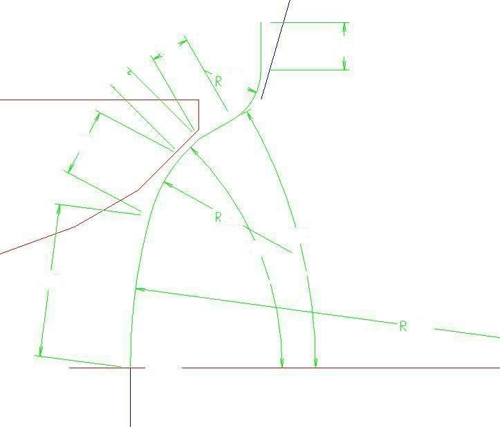
This pic I found on the internet illustrates what I'm talking about with the narrow valve angle, and the need to raise the exhaust ports to straighten the valve bowl to port exit line.
Intake is SWEET! It almost HAS no short side! The volume increase right at the bowl must just be an optical illusion as a volume change of that size doesn't seems right!
Exhaust SUCKS! You already know that, though. But like I've said I wouldn't mess with the floor. That would just worsen the angle. It looks pretty obvious the roof needs to be raised. Old fashioned drag racing exhuast port work of welding the floor and raising the roof to facilitate exhuast flow. Packaging is the problem here.
Shit, I might have to trade in my bimmer.
|
Y2KZX12R
Needs a job
CompetitionCNC.com
Posts: 3762
|
posted November 03, 2007 03:49 AM
Larry, I've collected a ton of data but haven't started on the development yet. I won't be able to digitize the head for a month or so. I'll need the digitized data to move forward with this.
The data can vary with a flow bench when you do manual calcs. We use a flowcom computer that takes into account barometric pressure, temp, test pressure while it's taking 10 snapshots of the test at each lift. It does the calcs and averages out the 10 samples for a corrected average. It makes repeatability excellent vs. trying to eyeball the manometer, temp and control test pressure with the valve all at the same time to get one reading. The manometer is always bouncing a little and the air temp slowly rises from the motors pumping the air. It's actually all constantly changing during a test. This is why a flow com computer hooked to a laptop can actually measure 1 or 2 cfm changes accurately while without the flowcom your ball parking it all he time. We have two flow benches, a 110 and a 600 with the flow com. We have been using the 110 for 20 years but the sf600 with the flow com is WAY faster and WAY more accurate when you're talking tiny changes in cfm.
For testing at low, low lift from .020" in .020" increments at very high test pressures the 110 can't compare, that's where the flow com really shines too.
I'll know more when I really dig into the 14 head. So far I just started to collect some data.
I'm actually working on an L-92 GM gen IV head right now for the big cube drag guys. I have to get that finished for the first week in December. Then the zx14 head will move to the front burner.
Smokin, that sounds excellent. I'll need a tester for the zx14 head and you are a perfect canedate. You seem very consistent and that's what's needed. Let's discuss this more in about a month when I actually have a better idea as to when I'll have a preliminary design done. I have a head for testing so that's not a problem.
JW, the 12r had the same included valve angles and flowed much better as does the busa. So it's not the actual valve angles that are causing the low flow numbers but rather compromises in port design. Emissions come to mind...
Do you have a higher resolution version of that pic? You can't really see the ski jump in that pic. Either that or it was massaged for the sectional bikes photos for some reason?
I wish I had taken a pic of it before I sent the head off to get a fixture plate made. I won't have the head back for a few weeks now. But I'll get some pics when it gets back here.
____________
Y2KZX12R
CompetitionCNC.com
|
larryc
Novice Class
Posts: 43
|
posted November 03, 2007 05:05 AM
With 33.4mm intake and 28.3mm exhaust valve sizes, the convergance areas are:
Curtain Area -to- Valve Area Convergence Intake Valve Lift inch= .329
Curtain Area -to- Valve Area Convergence Exhaust Valve Lift inch= .278
Intake flow chart shows the flow gain / valve lift, begin to taper off at .250" valve lift...no question about that. However, it should not be due to convergance area. That area is based on lift and valve size and is not tied to any specific lift for all heads. It's .25 * valve diameter (1.315 * .25 = .32875)
Keep in mind that flowing a head at 10" may not reveal a problem that might show up at 28" or 36". Converted flow numbers are not extremely useful in analyzing a port's true behavior.
That .250" dip in flow gain may be tied to something like the center divider causing some turbulence. What does the port sound like at 10" of pressure @ .250" lift compared to 28" @ .250" lift....[see what I'm getting at here] Is it whistleing like mad? Is it pulsing?...etc...
I've had 4v heads with bad port dividers that would drive you right out of your skin from the noise at higher test depressions. Radiusing the divider calmed them down and pickd up a few CFM as well [ whole 'nother debate on the sharp vs radiused divider issue]
What is the throat size to valve size ratio for the intakes? They tend to be on the conservative side from the factory and generally, if you're after that midrange punch everyone loves so much, 88% is about right. If you're after those high lift CFM numbers then 90% is what you're after.
How were these tests conducted?
Was the intake flowed with the stock intake boot installed ?
Was the exhaust flowed bare or with a stub pipe?
If pipe, how long was it?
It would be good to flow the intake with the full intake tract installed - head w/ TB and even the airbox if possible? I'm estimating about 181CFM @28" from the full assembly . Anyone got the actualy number?
Anyway...'nuff for this morning..I have work to do...Looking forward to hearing your guys opinions on this 14 head....or any other motor for that matter..
Best Regards,
Larry C
|
smokinzx14
Needs a life
Posts: 10197
|
posted November 03, 2007 06:26 AM
quote:
Larry, I've collected a ton of data but haven't started on the development yet. I won't be able to digitize the head for a month or so. I'll need the digitized data to move forward with this.
The data can vary with a flow bench when you do manual calcs. We use a flowcom computer that takes into account barometric pressure, temp, test pressure while it's taking 10 snapshots of the test at each lift. It does the calcs and averages out the 10 samples for a corrected average. It makes repeatability excellent vs. trying to eyeball the manometer, temp and control test pressure with the valve all at the same time to get one reading. The manometer is always bouncing a little and the air temp slowly rises from the motors pumping the air. It's actually all constantly changing during a test. This is why a flow com computer hooked to a laptop can actually measure 1 or 2 cfm changes accurately while without the flowcom your ball parking it all he time. We have two flow benches, a 110 and a 600 with the flow com. We have been using the 110 for 20 years but the sf600 with the flow com is WAY faster and WAY more accurate when you're talking tiny changes in cfm.
For testing at low, low lift from .020" in .020" increments at very high test pressures the 110 can't compare, that's where the flow com really shines too.
I'll know more when I really dig into the 14 head. So far I just started to collect some data.
I'm actually working on an L-92 GM gen IV head right now for the big cube drag guys. I have to get that finished for the first week in December. Then the zx14 head will move to the front burner.
Smokin, that sounds excellent. I'll need a tester for the zx14 head and you are a perfect canedate. You seem very consistent and that's what's needed. Let's discuss this more in about a month when I actually have a better idea as to when I'll have a preliminary design done. I have a head for testing so that's not a problem.
JW, the 12r had the same included valve angles and flowed much better as does the busa. So it's not the actual valve angles that are causing the low flow numbers but rather compromises in port design. Emissions come to mind...
Do you have a higher resolution version of that pic? You can't really see the ski jump in that pic. Either that or it was massaged for the sectional bikes photos for some reason?
I wish I had taken a pic of it before I sent the head off to get a fixture plate made. I won't have the head back for a few weeks now. But I'll get some pics when it gets back here.
Sounds good .. Just let me know when you are ready ...Smokin..
____________
Smokin Performance Cycles..
Tampa Bay , FL .. Brocks Performance Dealer ..
Gen 2 ZX14R Best ET 8.43 , Best MPH 164.95
|
SteddyTeddy
Pro
Posts: 1664
|
 posted November 03, 2007 06:51 AM

|
larryc
Novice Class
Posts: 43
|
posted November 03, 2007 08:39 AM
Edited By: larryc on 3 Nov 2007 09:46
There's a really good closeup of the exhaust port on this site. The thread is "Doug Meyer Disects the ZX-14 Engine"
I agree, digital testing is the best. My bench is digital as well. I created my own software that does in depth calculations of Coefficiencies, velocity and CFM/Sq.in -valve area. It's also got a port mapping feature for live, pitot captured velocity readings and outputs in actual Feet Per Second...click of the mouse..flow capture...click of the mouse...velocity capture...works great. It works with the FP1 flow processor. Google "FPEXCEL"
That exhaust port is tempting to address because of the low flow numbers. To prove it though will require modifying ONLY the ehauxt port followed by dyno testing....then off with the head again for the intake side....time consuming, definitely. Worth the effort, absolutely.
But before I hauled out the carbide, I'd get some good velocity readings of that port and see just how far down the floor is actually low or dead. Next I'd measure the throats and if they're not 90%, open them up straight away, then retest.....I know you've got your own methods for processing....just commenting on my opinion...certainly not dictating to you on what / how it should be done...
I don't know that I'd raise it a bunch without seeing the stock approach to the header pipe but more likely look at widening the roof somewhat starting back near the ssr apex and tapering outward from there. Something in the neighborhood of 100% - 104% of valve area for port exit area should do the trick...again...JMO
Best Regards,
Larry C
quote:
quote:
Larry, I've collected a ton of data but haven't started on the development yet. I won't be able to digitize the head for a month or so. I'll need the digitized data to move forward with this.
The data can vary with a flow bench when you do manual calcs. We use a flowcom computer that takes into account barometric pressure, temp, test pressure while it's taking 10 snapshots of the test at each lift. It does the calcs and averages out the 10 samples for a corrected average. It makes repeatability excellent vs. trying to eyeball the manometer, temp and control test pressure with the valve all at the same time to get one reading. The manometer is always bouncing a little and the air temp slowly rises from the motors pumping the air. It's actually all constantly changing during a test. This is why a flow com computer hooked to a laptop can actually measure 1 or 2 cfm changes accurately while without the flowcom your ball parking it all he time. We have two flow benches, a 110 and a 600 with the flow com. We have been using the 110 for 20 years but the sf600 with the flow com is WAY faster and WAY more accurate when you're talking tiny changes in cfm.
For testing at low, low lift from .020" in .020" increments at very high test pressures the 110 can't compare, that's where the flow com really shines too.
I'll know more when I really dig into the 14 head. So far I just started to collect some data.
I'm actually working on an L-92 GM gen IV head right now for the big cube drag guys. I have to get that finished for the first week in December. Then the zx14 head will move to the front burner.
Smokin, that sounds excellent. I'll need a tester for the zx14 head and you are a perfect canedate. You seem very consistent and that's what's needed. Let's discuss this more in about a month when I actually have a better idea as to when I'll have a preliminary design done. I have a head for testing so that's not a problem.
JW, the 12r had the same included valve angles and flowed much better as does the busa. So it's not the actual valve angles that are causing the low flow numbers but rather compromises in port design. Emissions come to mind...
Do you have a higher resolution version of that pic? You can't really see the ski jump in that pic. Either that or it was massaged for the sectional bikes photos for some reason?
I wish I had taken a pic of it before I sent the head off to get a fixture plate made. I won't have the head back for a few weeks now. But I'll get some pics when it gets back here.
Sounds good .. Just let me know when you are ready ...Smokin..
|
Y2KZX12R
Needs a job
CompetitionCNC.com
Posts: 3762
|
posted November 05, 2007 10:37 AM
Edited By: Y2KZX12R on 5 Nov 2007 10:43
quote:
I've had 4v heads with bad port dividers that would drive you right out of your skin from the noise at higher test depressions. Radiusing the divider calmed them down and pickd up a few CFM as well [ whole 'nother debate on the sharp vs radiused divider issue]
What is the throat size to valve size ratio for the intakes? They tend to be on the conservative side from the factory and generally, if you're after that midrange punch everyone loves so much, 88% is about right. If you're after those high lift CFM numbers then 90% is what you're after.
How were these tests conducted?
Was the intake flowed with the stock intake boot installed ?
Was the exhaust flowed bare or with a stub pipe?
If pipe, how long was it?
Yea the 4 valve heads witht he sharp deviders wistle like mad. Very annoying. I prefer the edge broken to reduce turbulance. That wistle is turbulance. The Busa head is at 89%, factory was about 87.7%. We typically test at 28" and we use a clay opening. Exhaust is with a 1.5" dia pipe 2.5" long. A stub pipe stablizes the port so we always test with a stub pipe.
____________
Y2KZX12R
CompetitionCNC.com
|
|
|
 HOME
HOME NEW TOPIC